RG35xx Replacement Buttons Install Guide
In this RG35xx replacement buttons install guide, I will be guiding you through the process of replacing the front face buttons on the RG35xx.

RG35xx replacement buttons can be purchased from a number of sources through Etsy, but the ones that I will be using in this guide are the SNES US style buttons from Sakura RetroModding.
When installed correctly, the buttons feel exactly the same as the original ones but can make your device look much better to suit your style.
If you are interested in replacing the RG35xx shoulder buttons, you can grab a set from the Get Better Buttons Etsy shop.
I have created a guide on replacing the shoulder buttons for the RG353V here, but the process is exactly the same for the RG35xx. Just be sure to grab the RG35xx shoulder buttons as the RG353V buttons will not fit.
Before you open your device, I will caution you that the RG35xx replacement buttons modification for the face buttons is a bit more complicated than replacing the shoulder buttons. However, with some patience, the end result will be an RG35xx that is uniquely yours.
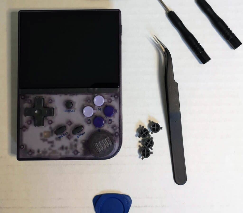
Tools you’ll need
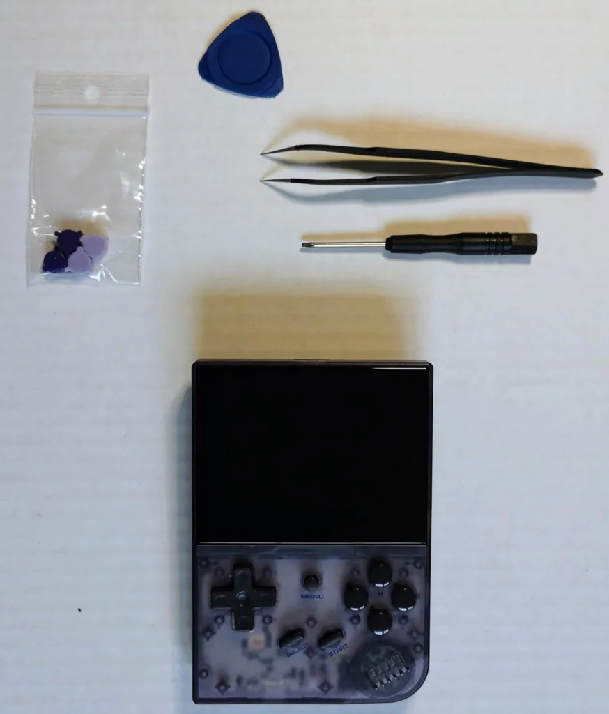
I recommend that you pick up a good tool kit that includes the screwdriver, tweezers and separator like this one from Amazon
- Small Philips head Screwdriver
- Torx T6H Screwdriver
- Guitar Pick
- Tweezers
- Replacement Face buttons
- Small bowl for the screw
RG35xx Tear Down
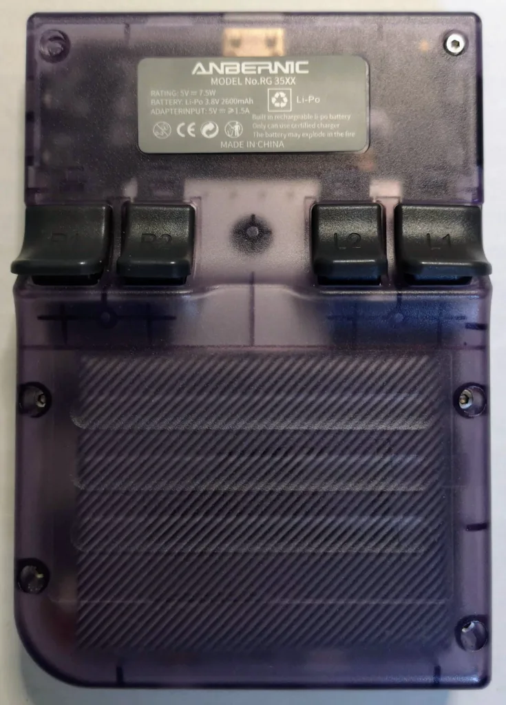
To open the RG35xx, first place the device face down on a flat surface.
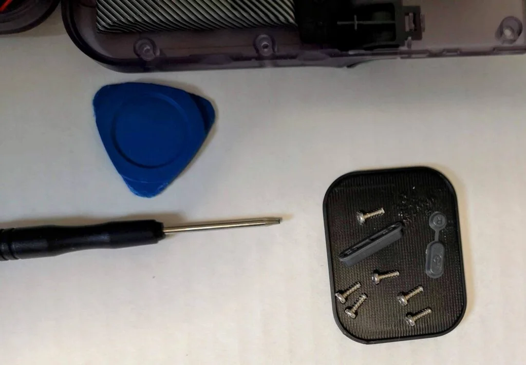
The back plate is held is place by six small Torx T6H screws which can be removed with your screwdriver by turning the screws in a counter clockwise direction.
Carefully remove the screws and place them in a small dish off to the side so that you don’t lose them or have them roll away.
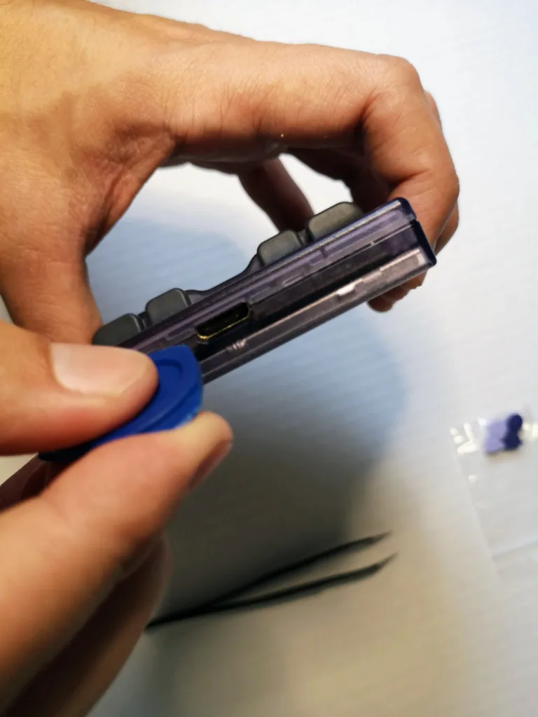
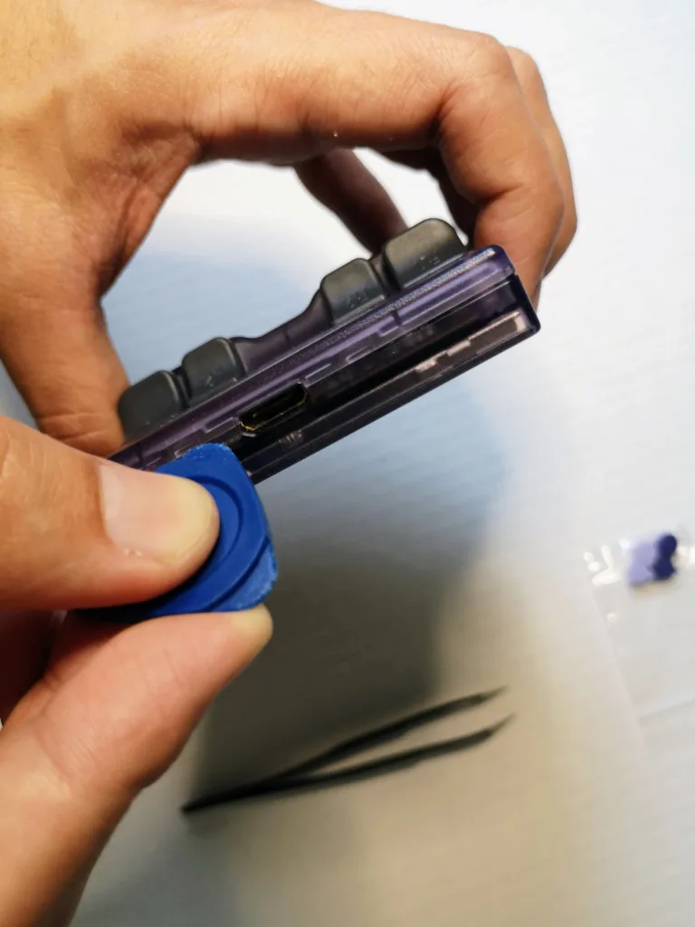
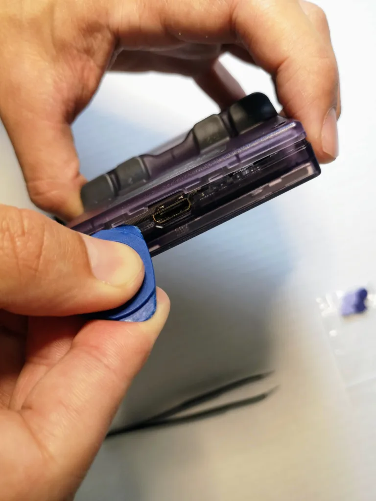
Now that the screws are removed, the next step is to carefully remove the back plate by prying it open with your guitar pick or separator. To do this, place the guitar pick near the HDMI port at the top of the device and use the small space between the port and the case to get some leverage for your separator.
Now, gently twist the guitar pick until you hear a small pop as the first snap holding the case together is released. Use this opening to work your way along the opening around the case releasing each of the hold points with a gentle twisting motion.
Once each of the snaps has been released, with the screen face down carefully open the device from the top as there is a wire at the bottom of the device connecting the battery on the back plate to the main board on the front plate.
With the device open, gently place it back down on the table. I recommend removing the volume and power/reset button covers and putting them to the side so that you don’t lose them as they are prone to fall out easily as we work with the device.

Removing the Main Board
Now that we have the RG35xx open, the next task is to get to the front face plate where the face buttons are. To do this, we need to detach the main board from the front face plate.
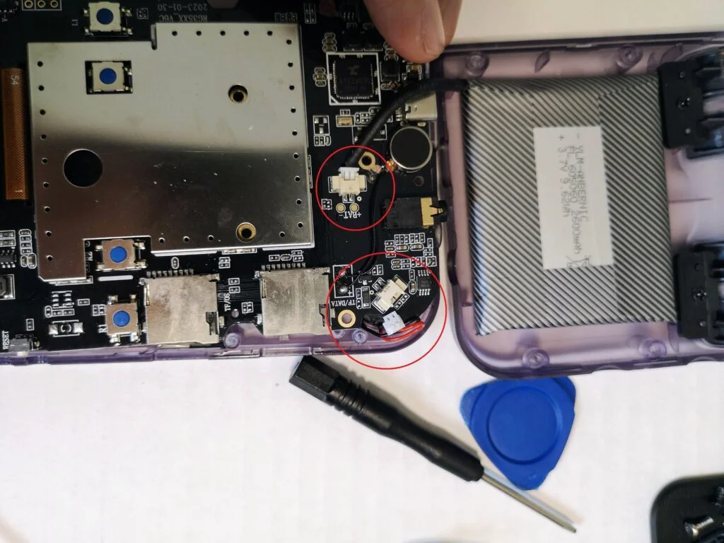
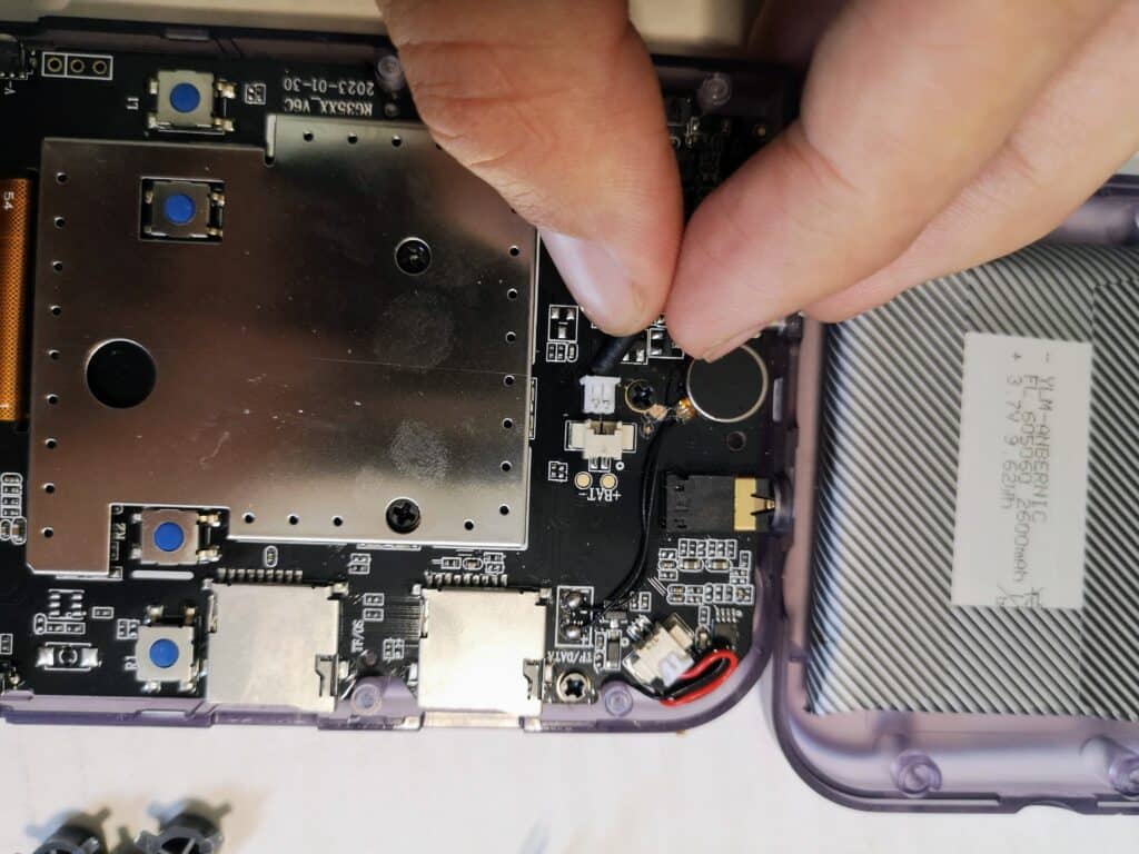
Before working with the main board, you will need to disconnect the battery and the speaker. Both of these wires are connected to an interface on the board and can be disconnected by working the head of the wire interface back and forth until it comes free of the main board interface.
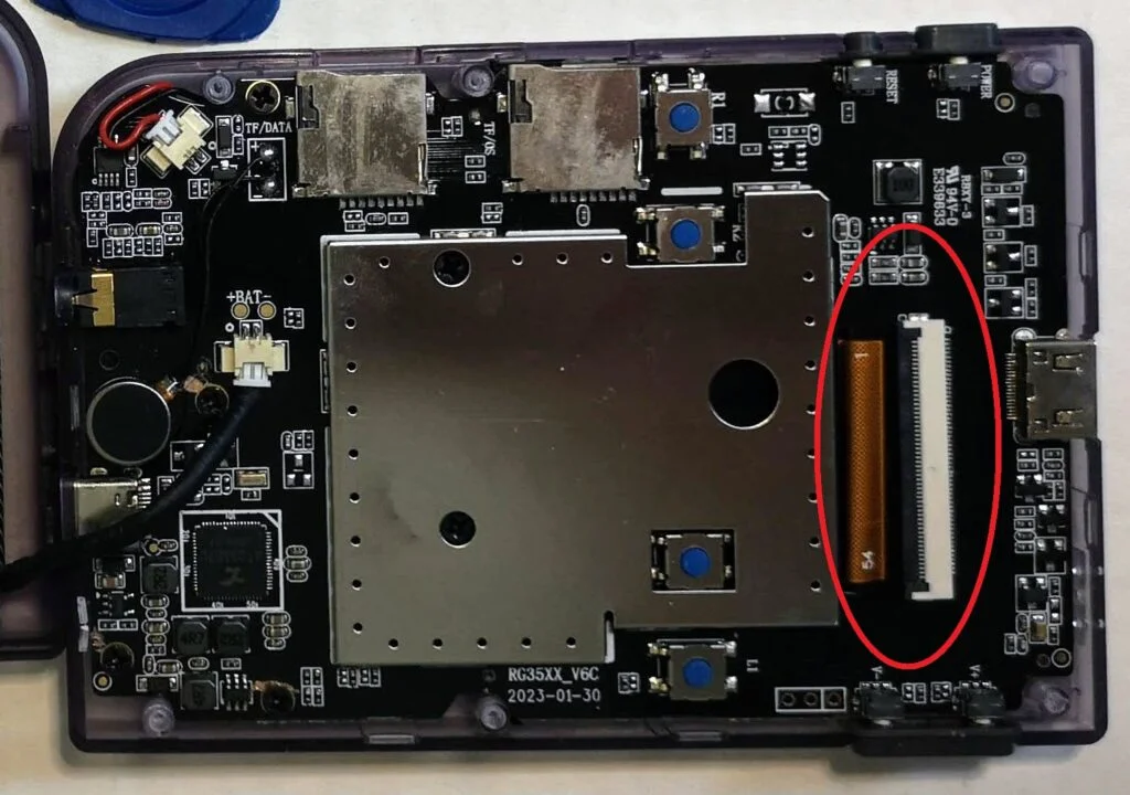
Optional: Disconnect the video cable from the main board for easier access to the front face plate. I did not do this step as it isn’t completely necessary, however, it does make it easier to access the front plate with the buttons if you completely remove the main board.
To disconnect the video cable ribbon from the main board, lift the black latch on the interface of the ribbon cable. The cable can then slide out of the interface and be threaded through the main board.
The main board is connected to the front face plate with five philips head screws.
Remove these screws and put them aside in a dish so as not to lose them.
With the screws removed, you can then lift the board very carefully out of the front face plate. If you left the video cable ribbon attached, you will not be able to completely remove the board, but you will be able to lift it from the bottom to expose the area where the button are.
The USB and headphone jack interfaces are recessed into the front face plate so you will need to push the entire board towards the top of the case to allow for the USB and headphone jack interfaces to come away from the front plate.

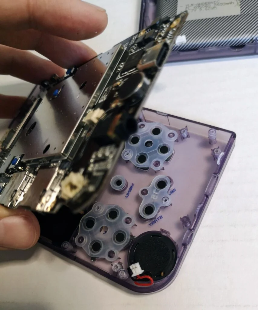

Replacing the buttons
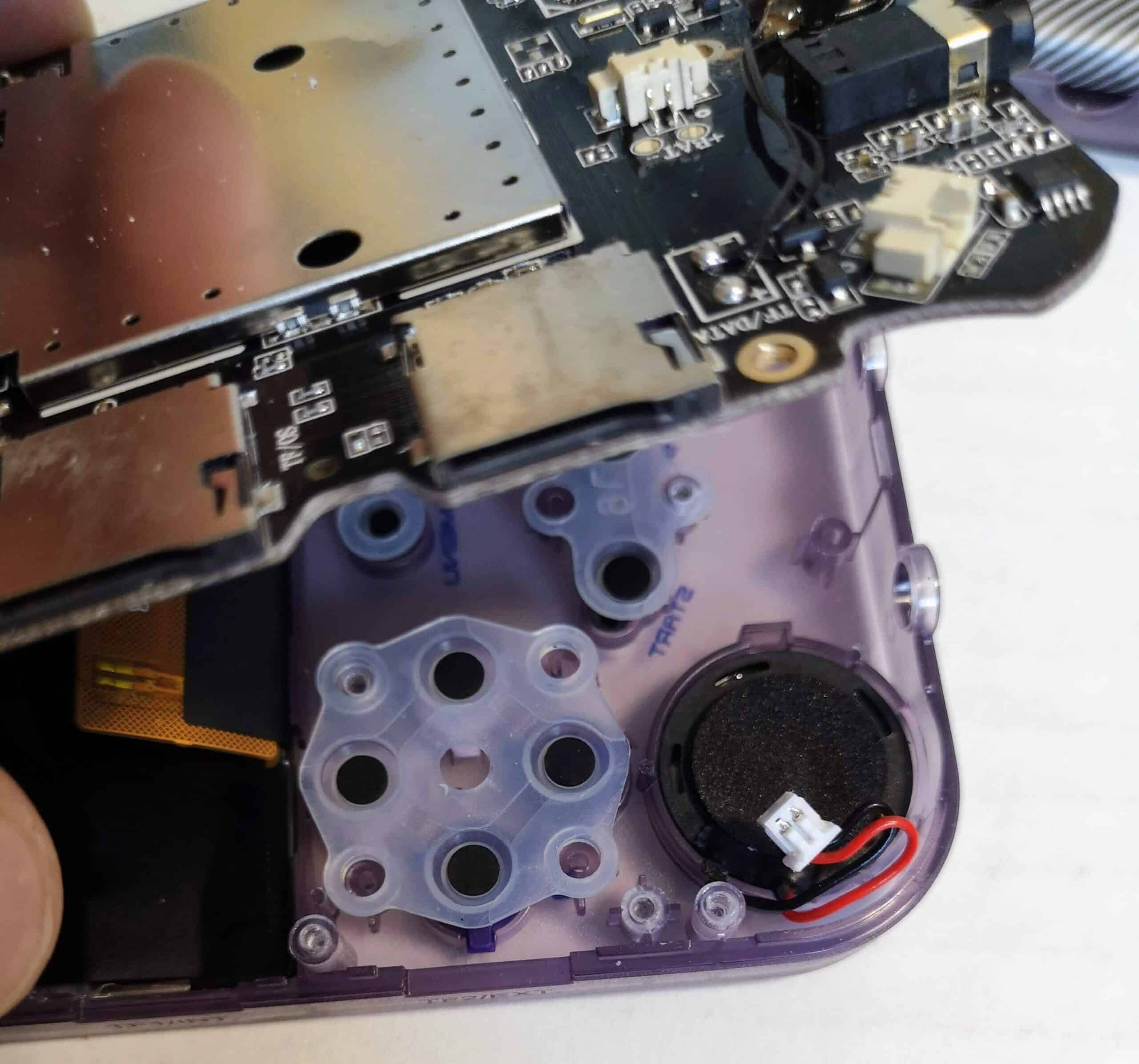
The buttons should now be exposed as you lift the main board out of the case. Each set of buttons will be covered with a rubber membrane. The face buttons that I am replacing for this guide are on the left side in the picture above.
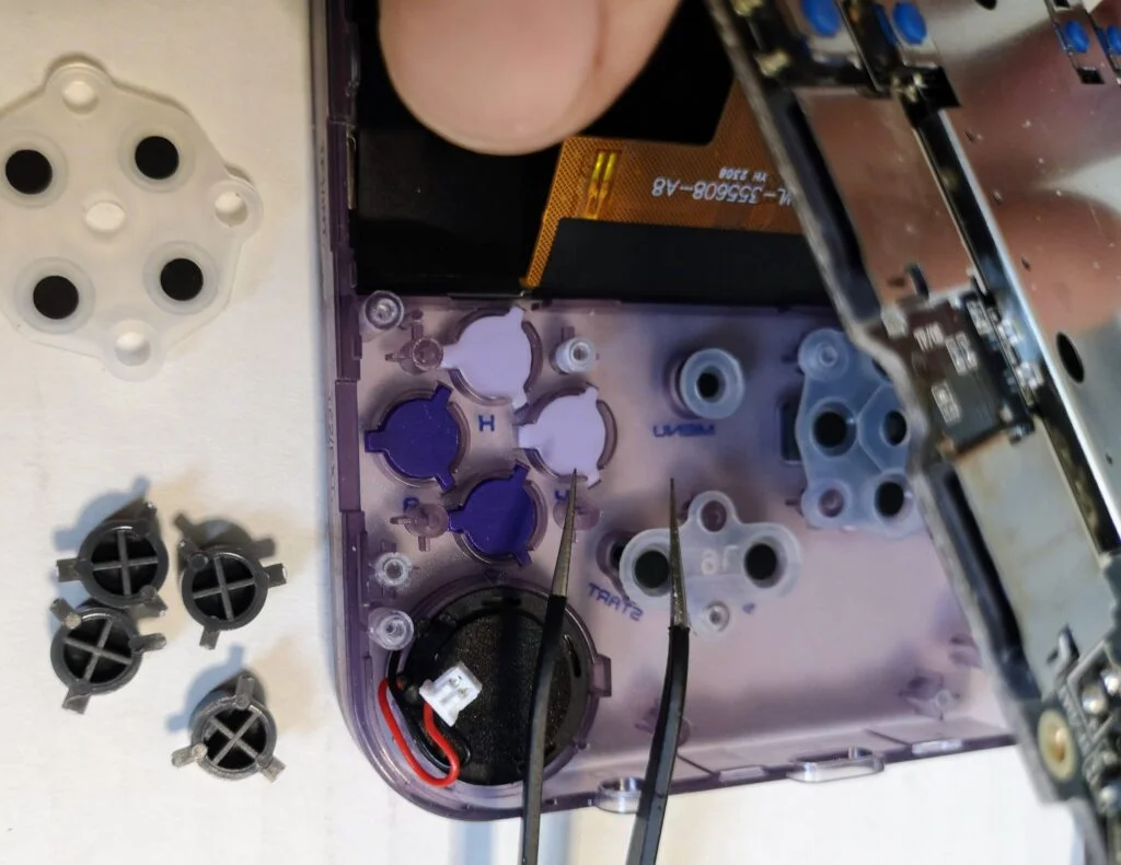
First we need to remove the rubber membrane from the set of buttons that are going to be replaced. The membrane is attached to the case via four posts which fit into the membrane. The membrane can easily be lifted off and set aside.
With the buttons exposed, you can lift them out with a pair of tweezers and set them aside. At the same time, you can begin to place the new buttons into their proper place back in the case.
Note that each button has three stems which line up against three divots in the case. One of these stems is wider than the other two and therefore each button can only fit into the case in a specific orientation.

With the new buttons in place, put the rubber membrane back over the buttons by lining up the holes against the posts on the case and pressing down on each hole until the post pokes through. I found it easiest to do this with a pair of tweezers by pressing down on the hold around the post.
Putting the RG35xx back together
Now it is time to put it all back together again.
First, if you removed the video cable, slide it back through the main board now.
Place the main board back in the case. Remember that the USB and headphone jack interfaces both have to be slid back into the front case to be fitted into their holes on the bottom of the front plate
With the board back down in place, you can begin attaching the screws again to secure the board to the front plate.
Next, reattach the speaker cable and the video cable. The video cable needs to be slid into the interface with the black latch open. Use tweezers to push the cable in as far as it will go then close the black latch to lock the cable in place.
Now attach the battery cable back to the main board.
Don’t forget to replace the volume and power/reset button covers.
Reattach the back plate and replace the screws. Be sure not to screw them back in too tight as you are very likely to crack the case if you over-tighten.

Final Results
More Reading..
-
How to Download GarlicOS Box Art
GarlicOS is a fantastic custom firmware that greatly improves the experience on the RG35xx. It is lightweight and intuitive to use as well as pretty…
-
How to install GarlicOS on RG35XX
In this guide, I will show you the steps on how to install GarlicOS on your RG35xx device. The process is very easy and with…
-
RG35xx Batocera Lite and Koriki Guide
June 2023 – The developer porting Batocera to the RG35xx has stopped development and started working on a fork of Batocera called Koriki which is…
-
RG35xx Starter Guide
The RG35xx is Anbernic’s answer to the widely successful Miyoo Mini. The RG35xx covers the cheap, ultra portable segment of the retro handheld gaming market…
-
RG35xx Themes Installation Guide
It’s not hard to see why GarlicOS is the most popular custom firmware available for the RG35xx. In addition to being fast and vastly improves…
-
RG35xx Ports Installation Guide
While the RG35xx is primarily a handheld device designed to play games from home and handheld consoles, did you know that it can also play…