RG353V Hall Sensor Joystick Replacement Guide
In this RG353V Joystick replacement guide, I will show you how to replace the joysticks in this device. The joysticks in the RG353V and RG353VS are standard Switch Joycon compatible joysticks.
While the RG353M has hall sensor joysticks, the V/VS models do not but they can be upgraded to hall sensor joysticks including those made by Gulikit and Retroid. This guide would be applicable to both the RG353V and the RG353VS.
Opening your electronic device can seem intimidating if you’ve never played inside electronics, but with this guide, I will show you that it is a pretty quick and easy thing to do.
Tools you’ll need
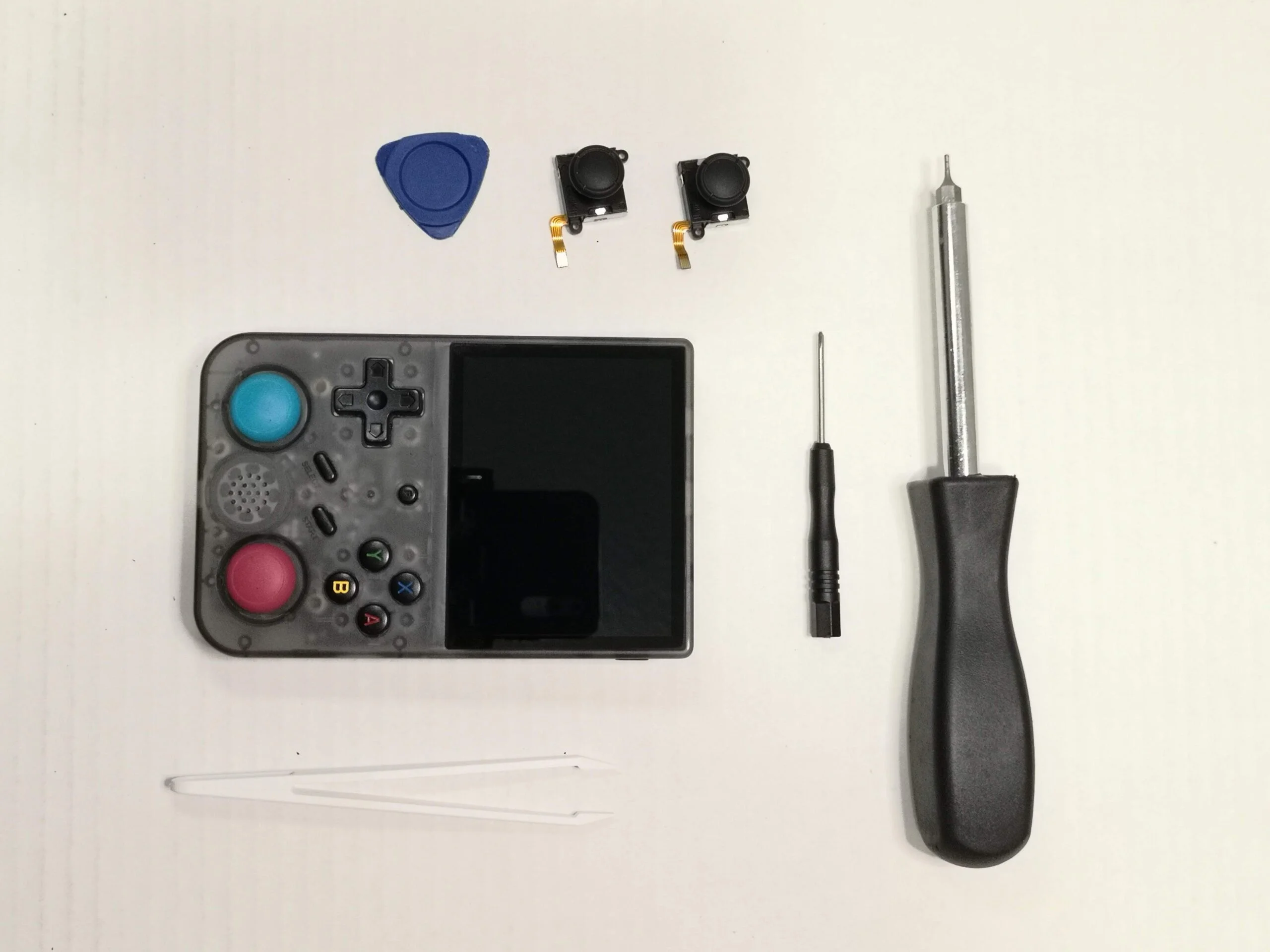
I recommend that you pick up a good tool kit that includes the screwdriver, tweezers and separator like this one from Amazon
- Small Philips head Screwdriver
- Torx T6H Screwdriver
- Guitar Pick
- Tweezers
- Joycon replacement Joystick (Gulikit Hall Sensor, or Standard Joycon Joystick)
- Small bowl for the screw
Opening your RG353V/VS
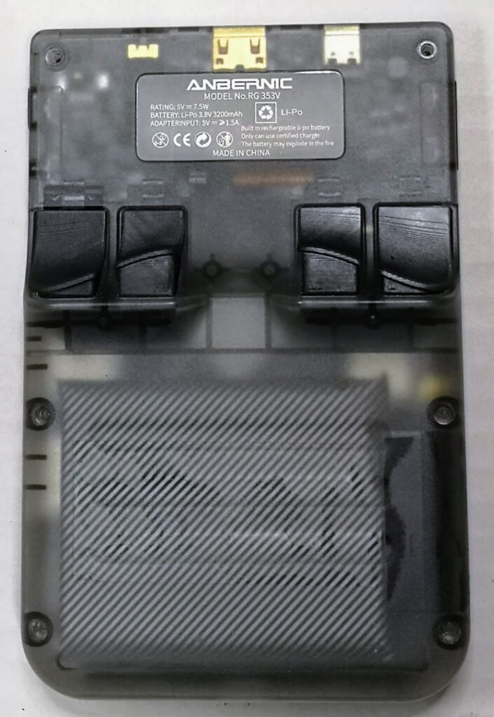
To open the RG353V, you first need to place the device face down on a flat surface.
The back plate is held in place by four small screws. Each screw needs to be removed carefully by turning the screw counter-clockwise with your screwdriver.
Put the screws aside. I recommend that you use a small dish to hold all of your screws so that they don’t roll off the surface that you are using.
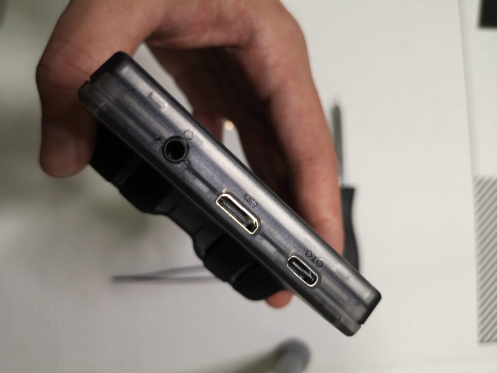
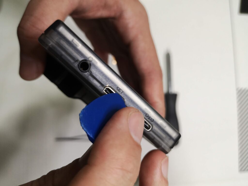
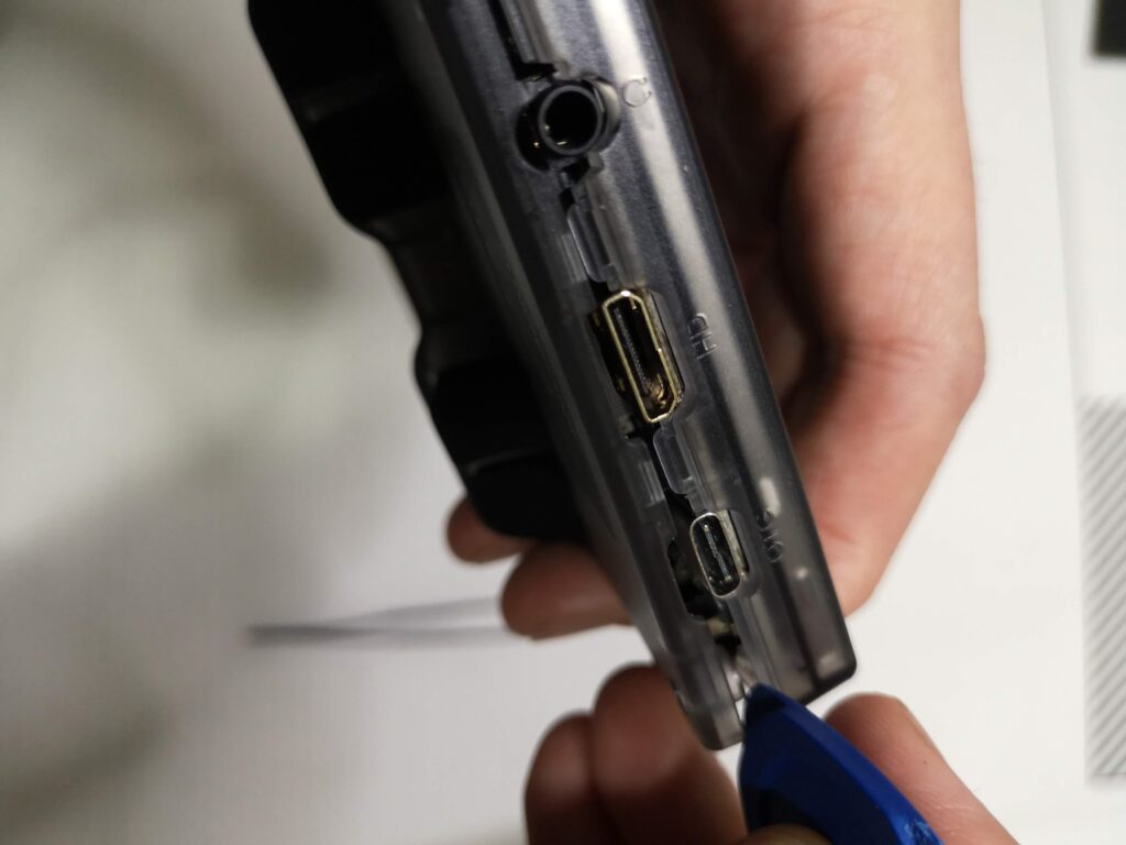
Next you need to remove the back plate carefully by prying it open with your guitar pick. To do this, insert your guitar pick in the gap between the HDMI port and the case. Carefully twist the guitar pick until you hear a small pop as the back plate releases from the front of the case. Use this opening to work your way along the opening around the case releasing each of the hold points.
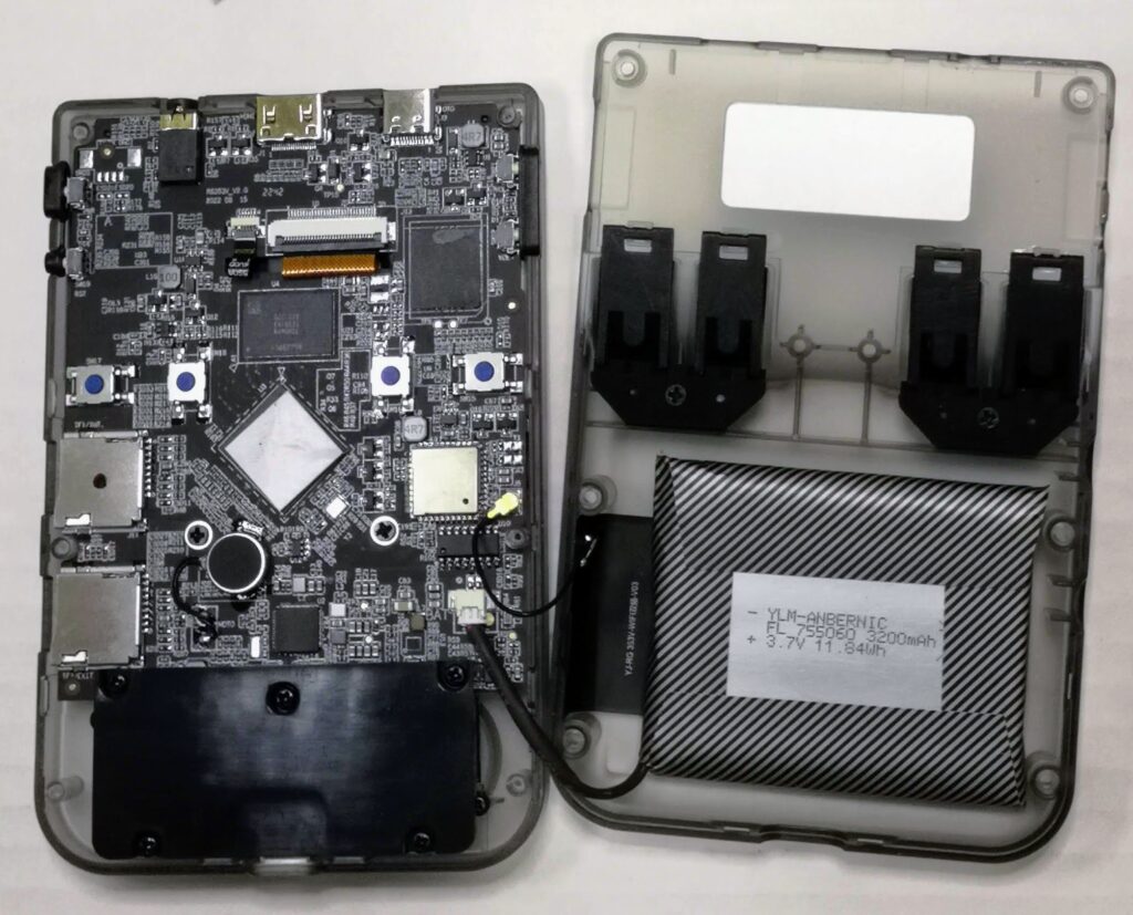
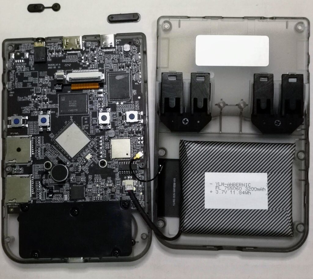
With the screen face down, remove the back plate carefully from the left side as there are wires connecting the wifi chip to the back plate and the battery to the main board.
Open the case slowly and set it down like an open book being careful not to lose the power and volume rocker buttons as they can fall out as they are not secured to the case. I recommend taking these buttons out and setting them aside so you don’t lose them.
You can place your RG353V back on the table face down.
Removing the old joysticks
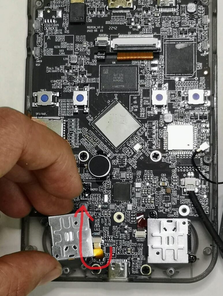
Next you need to locate the joysticks in your RG353V device. On the front of the device near the bottom you will notice a black plastic plate which is secured by five philips head screws. Use the philips head screwdriver to remove these screws and set them aside. You can now slowly lift the plastic plate off revealing the joysticks underneath.
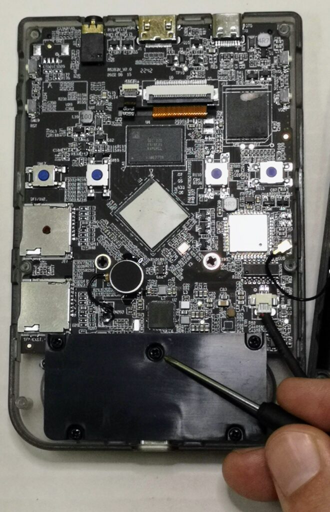
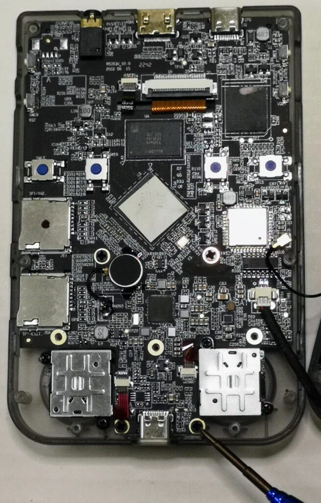
The joysticks are small square boxes connected to the main board by a very small ribbon cable. Each joystick is fastened to the main board by two small screws.
Before you unscrew the joysticks, you need to release the ribbon cable from the main board.
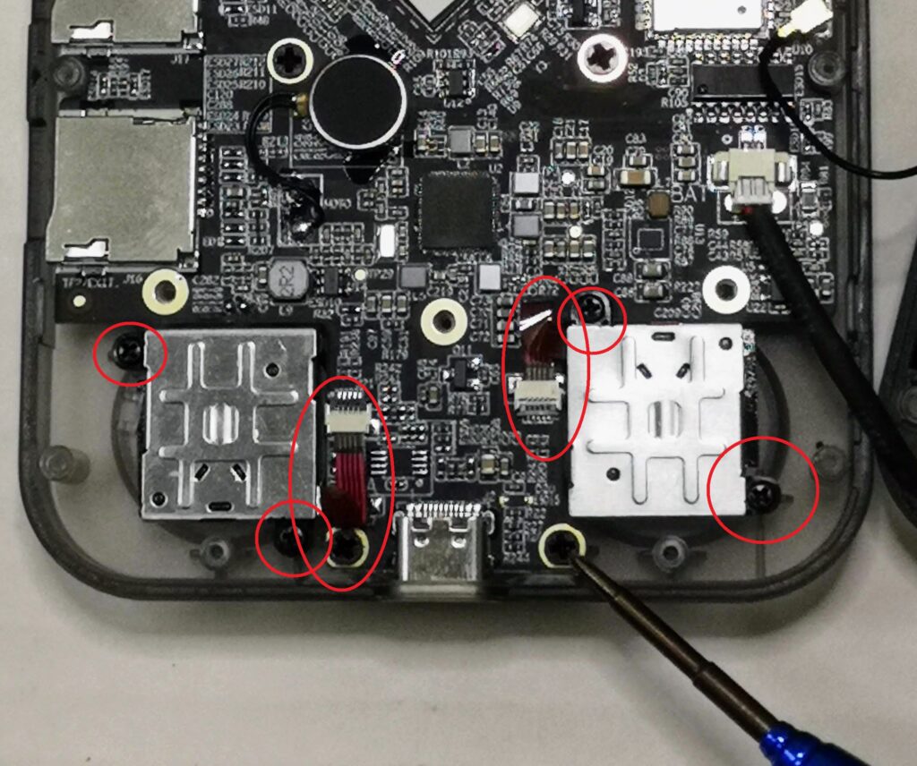
Each ribbon is connected to the board via a small white interface. The interface has a very small black latch on it which simply lifts like a very small switch. Use your tweezers to lift the latch carefully.
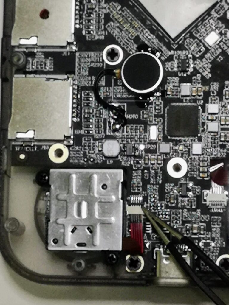
Once the latch is lifted, you can use the tweezers to carefully pull the ribbon from the interface. This should be very easy to do as long as the latch locking mechanism has been released. Do not force this.
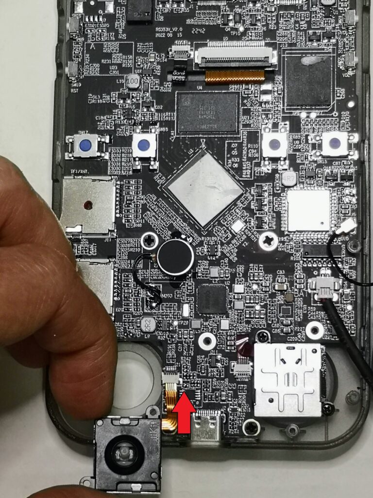
Now that the ribbon has been released, you can unscrew the joystick from the main board and carefully pull the joystick out of the case. The stock joysticks can easily be pushed through the opening. Be sure to put the screws aside but separate from the case screws as they are different sizes!
Repeat this same process for the second joystick then put both of your original joysticks to the side. Next we are going to put the new joysticks into the case and reattach them.
Inserting the new joysticks
I found the easiest way to insert the new joysticks is to insert the ribbon cable first then fold the cable over gently and push the joystick through the opening in the case.
To do this, orient your joystick face up so that the joystick cap is pointed up towards you as if you are going to put it in backwards.
Next, using your tweezers, insert the ribbon cable carefully into the interface and close the locking latch.
Now, flip the joystick over so that you can put it through the case the correct way, gently folding the ribbon in half in the process. Do not fold it too hard as you don’t want to break the ribbon cable.
Once the joystick is seated, carefully screw the joystick back down to the board. Do not over tighten the screws as you are likely to crack or damage the board if you screw it down too tight. Just enough until you feel it start to provide resistance as you turn the screw.
The same process repeats for the second joystick.
Putting the RG353 back together
Now that the new RG353V joysticks are in place, put the black plastic plate back in place and secure it to the board with the screws.
Ensure that the volume rocker and power button covers are back in place (make sure they are’t upside down!)
Place the back plate over the case and begin to press down on it around the edges. You should feel the case begin to snap back in place at the latches.
When the case is snug, you can put the screws back to secure the case.
Now that the case is back together, power on the unit and go into the joystick tester to check and calibrate your new joysticks.
If you enjoyed this guide, be sure to check out my RG353V Shoulder Button Replacement Guide
More Reading..
-
RG353 GammaOS Install Guide
If you have an RG353, GammaOS is an Android custom firmware option available for the RG353 dual boot devices such as the RG353V, M, P,…
-
RG353 Ports and PortMaster
While the RG353 is primarily designed as an emulation device targeted at retro home and handheld consoles, it is also capable of playing a number…
-
RG353 Dreamcast Best Settings Guide
When it comes to Dreamcast, the RG353 is capable of playing a good portion of the library but to get the best experience you’ll probably…
-
RG353V Shoulder Button Replacement Guide
In this RG353V Shoulder Button replacement guide, I will show you how to replace the back shoulder L1/R1/L2/R2 buttons in this device with the Better…
-
RG353 CFW Comparison Guide
The RG353 has a number of custom firmware options for Linux that give the device a new look and feel over the stock OS. Each…
-
RG353 PSP Performance Compatibility List
In this RG353 PSP Performance list I will show you my ratings of over 85 PSP games that I have personally tested on my RG353V…